

In modern society, scope of Electronics Engineering is very vast that applied in every field. Development of world that includes every area such as telecommunications, satellite, microelectronics etc are the outcome of talented engineers. ECE is all about working with electronic science & communication equipments such as mobiles, fridge, transmitters, fulfilling the daily requirements of the people. This incourage students to understand the concept and design of the devices and bring new out innovations.
These programme are aimed at providing students with a sound knowledge in the theoretical aspects and practical working knowledge in the field of Electronics Engineering. With the aim of bridging the gap between text-book knowledge and its practical application, the students are required to take lab classes on all core subjects in addition to seminars and projects.This course is structured in a way to provide better opportunities in industry and increase confidence and chance employment prospects. The core advantage of this field is to including designing and developing complex devices and systems. The program also raise students for a range of increasing career options around them.
Core Subjects
Subject code | Subject | Semester | Year |
AHT006 | Transformation and numerical method | 3rd | 2nd |
AHT007 | Technical Communication | 3rd | 2nd |
AHT008 | Universal Human Values | 3rd | 2nd |
ECT031 | Analog Electronic Circuit | 3rd | 2nd |
ECT032 | Networks & Systems | 3rd | 2nd |
ECT033 | Digital Electronics | 3rd | 2nd |
Lab | |||
ECP031 | Analog Electronic Circuit Lab | 3rd | 2nd |
ECP032 | Networks Lab | 3rd | 2nd |
ECP033 | Digital Electronics Lab | 3rd | 2nd |
ECP034 | Internship-I/Mini Project-I* | 3rd | 2nd |
CST005 | Cyber Security | 3rd | 2nd |
CST006 | Python Programming | 3rd | 2nd |
Subject code | Subject | Semester | Year |
AHT008 | Universal Human Values | 4th | 2nd |
AHT007 | Technical Communication | 4th | 2nd |
CST003 | Data Structure | 4th | 2nd |
ECT-041 | Analog Communication Systems | 4th | 2nd |
ECT-042 | Microprocessor & Microcontroller | 4th | 2nd |
ECT-043 | Electromagnetic field theory | 4th | 2nd |
Lab | |||
ECP-041 | Analog Communication Lab | 4th | 2nd |
ECP-042 | Microprocessor & Microcontroller Lab | 4th | 2nd |
CSP-003 | Data Structure Lab | 4th | 2nd |
CST006 | Python Programming | 4th | 2nd |
CST005 | Cyber Security | 4th | 2nd |
Subject code | Subject | Semester | Year |
ECT-051 | Antenna & Wave Propagation | 5th | 3rd |
ECT-052 | Digital Communication | 5th | 3rd |
ECT-053 | Semiconductor Devices | 5th | 3rd |
EEC-01X | PEC-1 | 5th | 3rd |
EEC-02X | PEC-2 | 5th | 3rd |
Lab | |||
ECP-051 | Integrated Circuit Lab | 5th | 3rd |
ECP-052 | Circuit Simulation Lab | 5th | 3rd |
ECP-053 | Soft Computing Lab | ||
ECP-054 | Mini Project-II or Internship-II* | 5th | 3rd |
Open Elective | |||
AST009 | Constitution of India | 5th | 3rd |
AST010 | Essence of Indian Traditional Knowledge | 5th | 3rd |
EEC-011 | Multimedia Communication | 5th | 3rd |
EEC-011 | Embedded Systems | 5th | 3rd |
EEC-011 | Computer Networks | 5th | 3rd |
EEC-011 | Design of Analog CMOS Integrated Circuits | 5th | 3rd |
EEC-021 | Power Electronics | 5th | 3rd |
EEC-022 | Artificial Neural Network and Fuzzy Logic | 5th | 3rd |
EEC-023 | IoT & Machine learning | 5th | 3rd |
EEC-024 | Electronics Measurement | 5th | 3rd |
Subject code | Subject | Semester | Year |
ECT-061 | Control Systems | 6th | 3rd |
ECT-062 | Digital Signal processing | 6th | 3rd |
ECT-063 | Microwave Engineering | 6th | 3rd |
EEC-03X | Departmental Elective – 3 | 6th | 3rd |
AHT011 | Open Elective-1 | 6th | 3rd |
Lab | |||
ECP-061 | Control Systems Lab | 6th | 3rd |
ECP-062 | Digital Signal processing Lab | 6th | 3rd |
ECP-063 | Microwave Lab | 6th | 3rd |
AST010 | Essence of Indian Traditional Knowledge | 6th | 3rd |
AST009 | Constitution of India | 6th | 3rd |
ECP-064 | Mini Project-III or Internship-III* | 6th | 3rd |
Open Elective | |||
EEC-031 | Probability Theory and Stochastic Processes | 6th | 3rd |
EEC-032 | Information Theory & Coding | 6th | 3rd |
EEC-033 | Radar and Navigation | 6th | 3rd |
EEC-034 | Analog Filter Design | 6th | 3rd |
Subject code | Subject | Semester | Year |
AHT015 | HSMC -1 | 7th | 4th |
AHT016 | HSMC -2 | 7th | 4th |
EEC-04X | Departmental Elective-4 | 7th | 4th |
EEC-05X | Departmental Elective-5 | 7th | 4th |
XXX-0XX | Open Elective-2x | 7th | 4th |
Lab | |||
ECP-071 | VLSI Design Lab | 7th | 4th |
PCT001 | Seminar | 7th | 4th |
ECP-072 | Design Project | 7th | 4th |
ECP-073 | Internship-III* | 7th | 4th |
Open Elective | |||
AHT017 | Disaster Management | 7th | 4th |
EEC-041 | CMOS Design | 7th | 4th |
EEC-042 | Mixed Signal Design | 7th | 4th |
EEC-043 | Micro-electromechanical Systems (MEMS) | 7th | 4th |
EEC-044 | Nano-electronics | 7th | 4th |
EEC-051 | Biomedical Signal Processing | 7th | 4th |
EEC-052 | Digital Image Processing and Applications | 7th | 4th |
EEC-053 | Advance Digital Signal Processing | 7th | 4th |
EEC-054 | Nano Materials | 7th | 4th |
Subject code | Subject | Semester | Year |
AHT016 | HSMC-2 | 8th | 4th |
AHT015 | HSMC-1 | 8th | 4th |
EEC-06X | Departmental Elective-6 | 8th | 4th |
XXX-0XX | Open Elective-3x | 8th | 4th |
XXX-0XX | Open Elective-4x | 8th | 4th |
Lab | |||
ECP-081 | Project | 8th | 4th |
Open Elective | |||
EEC-061 | Wireless Communications | 8th | 4th |
EEC-062 | Audio Speech Processing | 8th | 4th |
EEC-063 | Public Broadcast Engineering | 8th | 4th |
EEC-064 | Electronic Switching Systems | 8th | 4th |
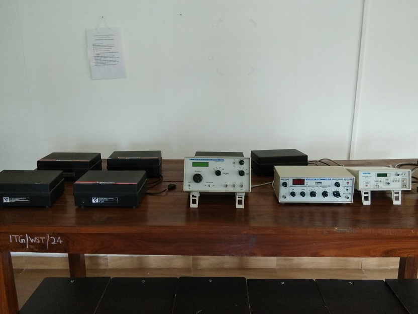
- DSB/SSB AM Transmitter Trainer (Scientech 2201)
- DSB/SSB AM Receiver Trainer (Scientech 2202)
- Frequency Modulation and Demodulation Trainer (Scientech 2203)
- Project Board (Scientech 2610)
- PPM Modulation and Demodulation Trainer (NV6577)
- PWM Modulation and Demodulation Trainer (NV6576)
- LAN Trainer (Scientech 5002A)
- Scientech 401 Digital Storage Oscilloscope 50MHz, 50MSa/s
- Scientech 806 60MHz Cathode Ray Oscilloscope
- 10MHz Function-Pulse-Data Generator (Scientech 4065)
- To study DSB/ SSB amplitude modulation & determine its modulation factor & power in side bands.
- To study amplitude demodulation by linear diode detector
- To study frequency modulation and determine its modulation factor
- To study PLL-565 as frequency demodulator.
- To study sampling and reconstruction of Pulse Amplitude modulation system.
- To study the sensitivity, selectivity, and fidelity characteristics of superheterodyne receiver.
- To study Pulse Amplitude Modulation by using switching method and sample and hold circuit.
- To demodulate the obtained PAM signal by second order LPF.
- To study Pulse Width Modulation and Pulse Position Modulation.
- Design and implementation of FM radio receiver in 88-108 MHz carrier frequency.
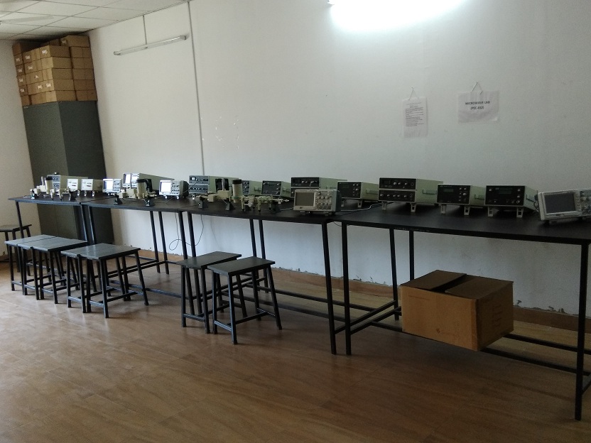
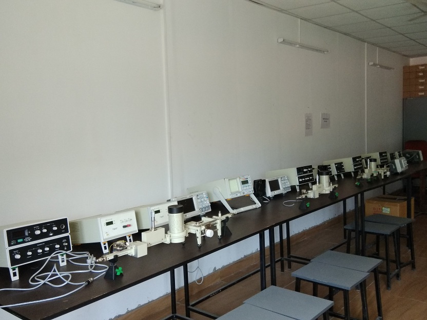
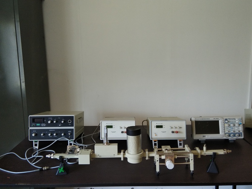
- Microwave Bench
- Gunn Power Supply NV 101A
- Klystron Power Supply Nvis 102A
- Frequency Meter Nvis 205A
- Variable Attenuator 20dB Nvis 206
- Isolator Nvis 204
- Detector Mount Nvis 209
- Matched Terminator Nvis 212
- Movable Short Nvis 210
- SWR Meter Nvis 103A
- To study of various microwave components and instruments like frequency meter, attenuator, detector & VSWR meter.
- Draw V-I characteristics of microwave source like Gunn diode/ Reflex Klystron.
- Measurement of frequency and wavelength in a rectangular waveguide.
- Measurement of VSWR (small as well as large values) & reflection coefficient.
- Measure unknown impedance with smith chart.
- Draw the following characteristics of Gunn Diode
- Output power and frequency as a function of voltage.
- Square wave modulation by PIN diode.
- Drawing polar pattern of Horn antenna.
- To observe the action of directional coupler and its use in separating incident & reflected wave.
- Universal Gate Trainer
- TTL Inverter Trainer
- Multivibrator Trainer Using IC-74121 and IC-74123
- Adder/Subtractor Trainer Using IC-7483
- Clocked Circuit Realization Trainer
- Demultipleaer/Decoder Trainer Using IC-74138
- Modulo-N Counter Trainer
- Flip-flop Trainer
- Shift Register Trainer
- Bread-board implementation of various flip-flops.
- Bread-board implementation of counters & shift registers.
- Determination of Delay time and NAND, NOR, Ex-OR, AND & OR Gates.
- Design of Counters.
- Implementation of Arithmetic algorithms.
- Bread Board implementation of half and full Adder/Subtractor.
- Transfer characteristics of TTL inverters & TTL Schmitt Trigger inverter.
- Transfer characteristics of CMOS inverters series and CD-40 series and
- Estimation of Gate delay of CD-40 series CMOS inverter.
- Monostable multivibrators using IC-74121 and IC-74123.
- Clock circuit realization using 555 and CMOS inverter and quartz crystal.
- Demultiplexer / Decoder operation using IC-74138.
- Analog Multimeter
- Voltmeter(0-2V,0-5V,0-100V,0-300V)
- Low Distortion Signal Generator
- Moving Iron Ammeter (0-100mA)
- Moving Iron Ammeter (0-10A)
- IC Regulated Power Supply
- Full Wave and Half Wave Rectifier Trainer
- Transistor Characteristics Trainer
- Logic Gates Trainer
- Breadboard
- ICs
- Digital Oscilloscope
- Digital Multimeter
- Cathode Ray Oscilloscope
- Basic Electronic Components(Diodes, Transistors, Resistors, Inductors, Capacitors)
- To study basic electronic Components and its measurements.
- To study instruments and equipments (DMM, Power supply, CRO).
- To study half wave and full wave rectifier circuits
- To study logic gates through breadboard implementation
- To study universal gates through trainer kit.
- To study the characteristics of PN-Junction diodes.
- To study the CB, CC and CE characteristics of bipolar junction transistor.
- To study operational amplifier and measurement of its various parameters.
- To study BJT amplifiers and its characteristics.
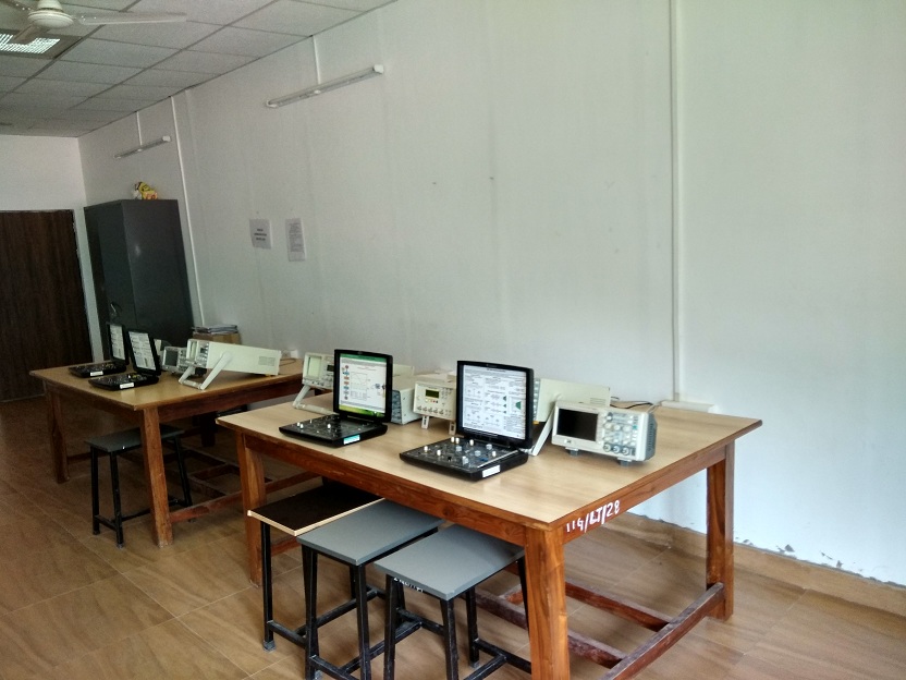
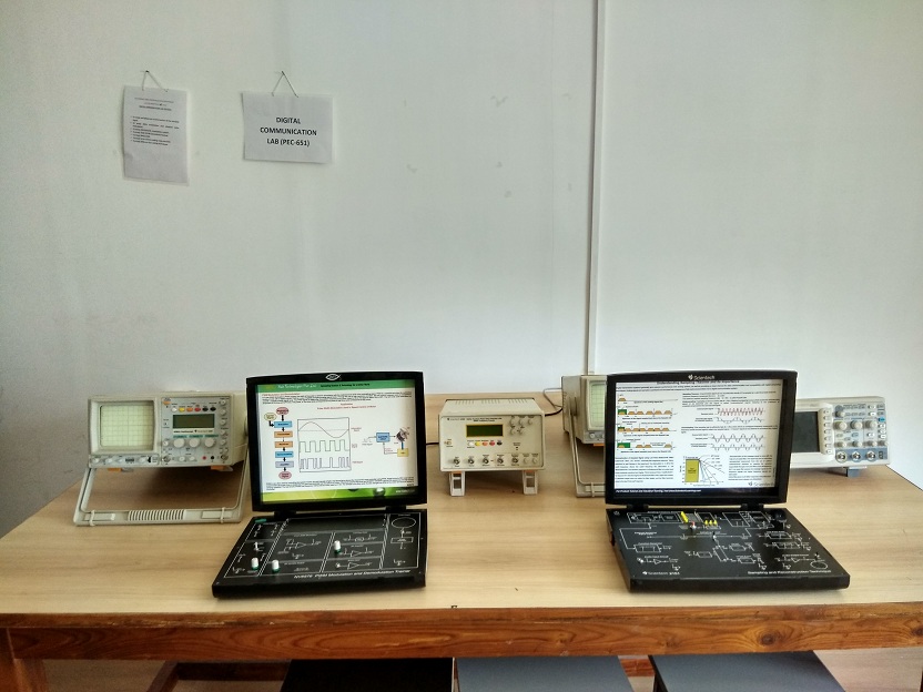
- TDM Pulse Code Modulation Transmitter Trainer(Scientech 2153)
- TDM Pulse Code Demodulation and Receiver Trainer(Scientech 2154)
- Sampling and Reconstruction Trainer(Scientech 2151)
- Delta Modulation and Demodulation Trainer(Scientech 2155)
- Data Formatting and Carrier Modulation Trainer(Scientech 2156)
- Data Reformatting and Carrier Demodulation Trainer(Scientech 2157)
- Scientech 401 Digital Storage Oscilloscope 50MHz, 50MSa/s
- Scientech 806 60MHz Cathode Ray Oscilloscope
- 10MHz Function-Pulse-Data Generator (Scientech 4065)
- To study sampling and reconstruction of the sampled signal
- To study modulation and demodulation Delta Modulation(DM) and Adaptive Delta Modulation(ADM).
- To study different digital modulation scheme.
- To Study modulation and demodulation of TDM/PCM Transmitter and Receiver.
- To Study DHSS, FHSS.
- To Study Error Control Coding technique using MATLAB Simulink.
- To Study different Line Coding Techniques.
- To study error detection and correction using Hamming code.
About
Digital Signal Processing Lab is used by electronics and communication students in a course on Digital Signal Processor. The lab has Texas Instruments DSP kits for carrying out various experiments. Software used in digital signal processing lab are MATLAB and LabVIEW. Test and measuring instruments are Digital Storage Oscilloscopes 10MHz, Function/ Pulse Generators 8 MHz and designing of various digital filters.
List of Equipments
- DSP Starter Kit for TMS 320 C6713
- Low Distortion Signal Generator
- Oscilloscope 50MHz Dual Channel Digital Storage
- Oscilloscope 25MHz Dual Channel Digital Storage
- Multisim
- Labview
List of Practicals
- To study of Sampling & Waveform Generation, Quantization of a analog signal.
- To study Pulse Coded Modulation(PCM) Techniques.
- To study Delta modulation and demodulation techniques.
- To study different Digital Modulation Schemes (ASK, PSK, FSK).
- To study computation of Discrete Fourier Transform(DFT).
- To study computation of Fast Fourier Transform(FFT).
- To study FIR Filter implementation, IIR Filter implementation.
- Computational Experiments with Digital bank of Filters.
- Echo Cancellation generation and Filters implementation.
- Low Distortion Signal Generator
- DC power supply (+/- 12V, 0-30V/2A, +/- 5V)
- Function Generator (FGL-9)
- Function Pulse Generator (UFG-10)
- Log and Antilog Amplifiers Using Operational Amplifiers Trainer
- Monostable, Bistable and Astable Multivibrator Using Transistor Trainer
- Distortion Meter SM5027
- Function Generator Using Operational Amplifier Trainer
- Low Distortion Audio Signal Generator (OW14D)
- Distortion Meter (DFM-20)
- FET Amplifier Trainer
- Emitter Follower Amplifier Using Darlington Pair
- Transistor Biasing Circuit Trainer
- Voltage Comparator Using Zero Crossing Detector Trainer
- Weinbridge Oscillator Using Op-Amp
- RC Coupled Amplifier Using BJT
- To study single stage common source, common drain and common gate FET amplifier.
- Design of single stage RC coupled amplifier and design of DC biasing circuit using potential divider arrangement.
- To study multistage amplifier and estimation of Q-factor and bandwidth.
- To study common collector configuration using Darlington pair.
- To study series and shunt feedback amplifier and determination of voltage and current gain.
- Design of weinbridge and phase shift oscillator on breadboard.
- Design of hartely and colpitts oscillator on breadboard.
- To study monostable, bistable and astable multivibrator using transistor.
- Fabrication of DC unregulated power supply.
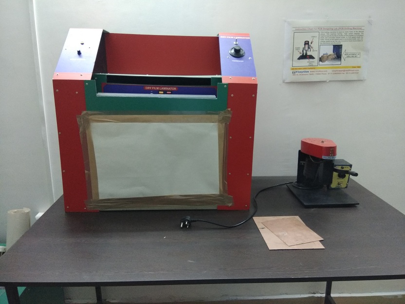
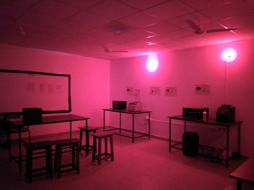
- PCB Lab:
- (a) Artwork & printing of a simple PCB.
- (b) Etching & drilling of PCB.
- (c) Testing of power supply fabricated in Experiment No. 6
- (d) Mini Project.
- Log and Antilog Amplifiers Using Operational Amplifiers Trainer
- Second Order LPF Trainer
- Second Order HPF Trainer
- Second Order BPF Trainer
- Monostable, Bistable and Astable Multivibrator Using IC-555 Timer Trainer
- Function Generator Using Operational Amplifier Trainer
- Phase Locked Loop Trainer
- DC power supply (+/- 12V, 0-30V/2A, +/- 5V)
- Voltage to Current and Current to Voltage Converter Using Op-Amp Trainer
- Hartely and Colpitts Oscillator Trainer
- Design of Log and antilog amplifiers.
- Design of voltage comparator and zero crossing detectors.
- Design of second order filters using operational amplifier for–
- Low pass filter of cutoff frequency 1 KHz.
- High pass filter of frequency 12 KHz.
- Band pass filter with unit gain of pass band from 1 KHz to 12 KHz.
- Design of wienbridge oscillator using operational amplifier.
- Determine capture range, lock in range and free running frequency of PLL.
- Design of voltage regulator using operational amplifier to produce output of 12V with maximum load current of 50mA
- Design of voltage to current and current to voltage convertors.
- Function generator using operational amplifier (sine, triangular & square wave)
- Astable and monostable multiviberator using IC-555 timer.
- PCB Design Software (TINA)
- ELVIS Board
- PCB Artwork File
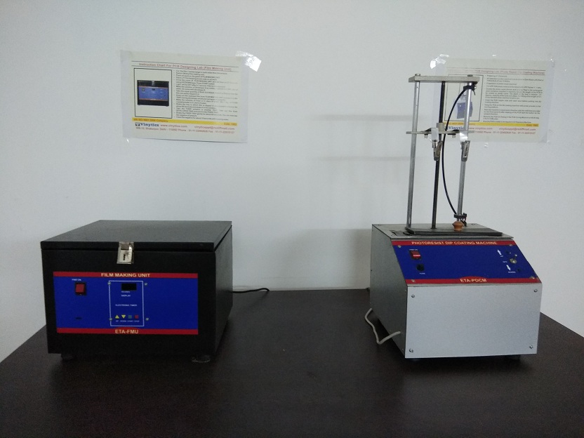
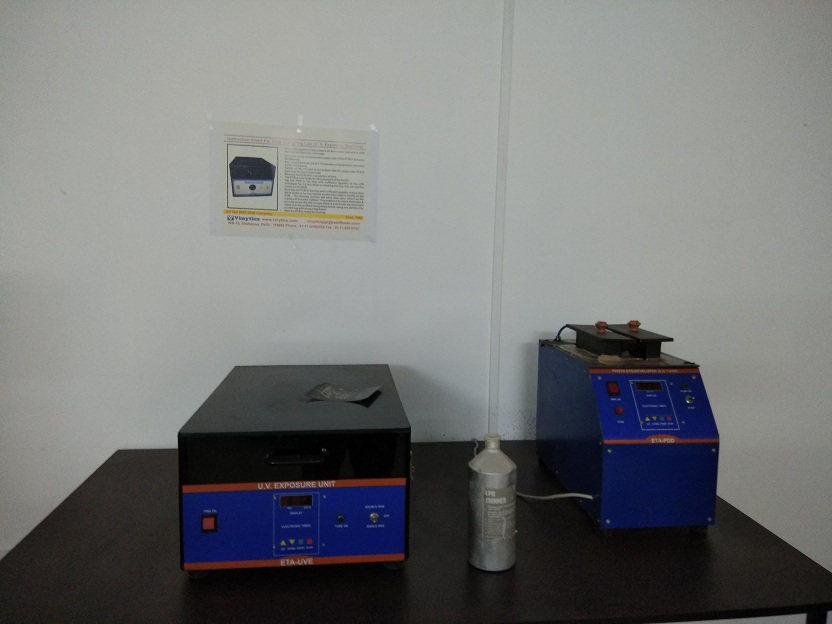
- Proto Dye Developer (2 in 1 Unit)
- Dip Coating m/c Dipcoater
- Double Sided U.V Exposure
- PCB Etching Machine
- PCB Drilling Machine
- Roller Tinning Machine(RTM 10)
- Dry Film Laminator
- Ammonical Etching Machine
- PCB Shearing Machine
- Three stages RC coupled common emitter amplifier and its testing for various parameters.
- Designing of Phase shift and Hartely Oscillators for variable frequency generation.
- Testing and designing of Class-A and Class-B push-pull amplifier.
- Testing and designing of Tuned amplifiers.
- Testing and designing of A to D and D to A convertor.
- Testing and designing of any Modulator and Demodulator Circuit.

Dr. Arun Uniyal
arun.uniyal@itgopeshwar.ac.in
M.No.: 9557279905
Ph.D (DIT University)
Designation:HOD & Assistant Professor

Arvind Kumar
arvind.kumar@itgopeshwar.ac.in
M.No.: 9456565663
Designation: Assistant Professor

Meenu Khanka
meenu.chinwan@itgopeshwar.ac.in
M.No.: 9997283834
M.Tech, (UTU Dehradun)
Designation: Assistant Professor
Click here for syllabus